
Conclusion
The premise of a label feeder is that the product can enter the pick-and-place machine. Plastic housings, metal parts, and molded modules cannot enter the pick-and-place machine, so labels on such products can only go another route. This module factory uses the LM402 multi-head vision labeling machine: products come in from the conveyor line, cameras find the position, the placement head picks up the label and presses it on, and the position is determined by vision, not by fixtures.
Production line and the original labeling method
This factory makes power and communication modules, and product forms are not fixed: there are potted plastic housings, stamped metal shields, and semi-finished products with connectors. Labels go on the housing surface, with sizes ranging from a few millimeters for QR codes to fifty millimeters for nameplates.
The original method was manual labeling plus fixture positioning. A set of positioning fixtures was made for each housing type, the product was placed inside, and the label was applied against the edge of the fixture. As variety increased, fixtures piled up into a wall; when new samples came out, fixtures could not be made in time, so manual visual labeling was used first, with position left to luck.
Selection: why the LM402
The LM402 is a multi-head vision labeling machine with a body of 950 × 950 × 1200 mm and a workpiece range of 1×1 to 50×50 mm, which exactly covers this factory’s largest nameplates.
Its positioning method is the key to this case: 6 cameras divide the work, 1 looks at the product datum, 4 look at small parts, and 1 looks at large parts; XY uses servo, and the Z axis is stepper. The product does not need to be placed very accurately; after the camera finds the datum point, the placement coordinates are corrected accordingly. The fixture therefore retreats from “the thing positioning depends on” to “only responsible for holding the product.”
On the feeding side, there are three feeder lane options: one 100 mm lane, three 60 mm lanes, or four 32 mm lanes. This factory chose three 60 mm lanes because the three commonly used label widths are all within 60 mm, and changeover only requires changing the roll.
Setup and debugging
Debugging is divided into two stages: first let the camera recognize the product, then let the placement head place accurately.
In the camera stage, datum features must be set. Plastic housings are mostly molded parts with clear edges and corners, so using the outer contour as the datum is enough; metal shields have reflective surfaces, and directly taking the contour will drift, so the relative relationship of two positioning holes was used as the datum instead. After this step, the placement angle deviation of the product at the station can be corrected.
In the placement stage, pressure and height are adjusted. The Z axis is stepper, and the pressing distance must be set according to the product surface material: plastic housings can be pressed down a little to make the label stick firmly, while metal parts will deform if pressed too much. When the label is a thin film type, a little time must be left between pickup and pressing so the label separates from the backing paper.
The optional code reading function was also used during debugging: the camera reads the barcode on the product, binds the label content to the product according to the specified format, and then uploads it to MES. The significance of this step for this factory is that the traceability chain is closed, and mislabeled material can be identified.
Changes after setup
Fixtures changed from “one set per product type” to a general placement fixture; new samples no longer need to wait for fixtures, and trial production can begin after adjusting the datum once. The manual labeling process was eliminated, and position consistency is determined by vision.
This factory subsequently put all three commonly used labels into the feeder lanes; during changeover, only the program is changed and the roll is replaced, with no equipment disassembly. Specific cycle time and yield are subject to customer statistics and are not cited in this article.
FAQ
What if the product size exceeds 50×50 mm? The LM402’s workpiece range is 1×1 to 50×50 mm, the placement area is X 100 mm × Y 500 mm, and the stroke can be customized as needed; anything beyond the range must be evaluated as a non-standard solution.
Does vision positioning require marks on the product? No special marks are needed; the product’s own outer contour or positioning holes can be used as the datum, and reflective materials require separate confirmation of the point-taking method.
Can it connect to MES? Code reading and uploading are optional functions, configured according to the required barcode format.
To evaluate according to your product form and label specifications, contact us directly: Kenny Pan · Sales Manager · Phone/WeChat +86 134 2139 1163 · Sales@baxida-tech.com
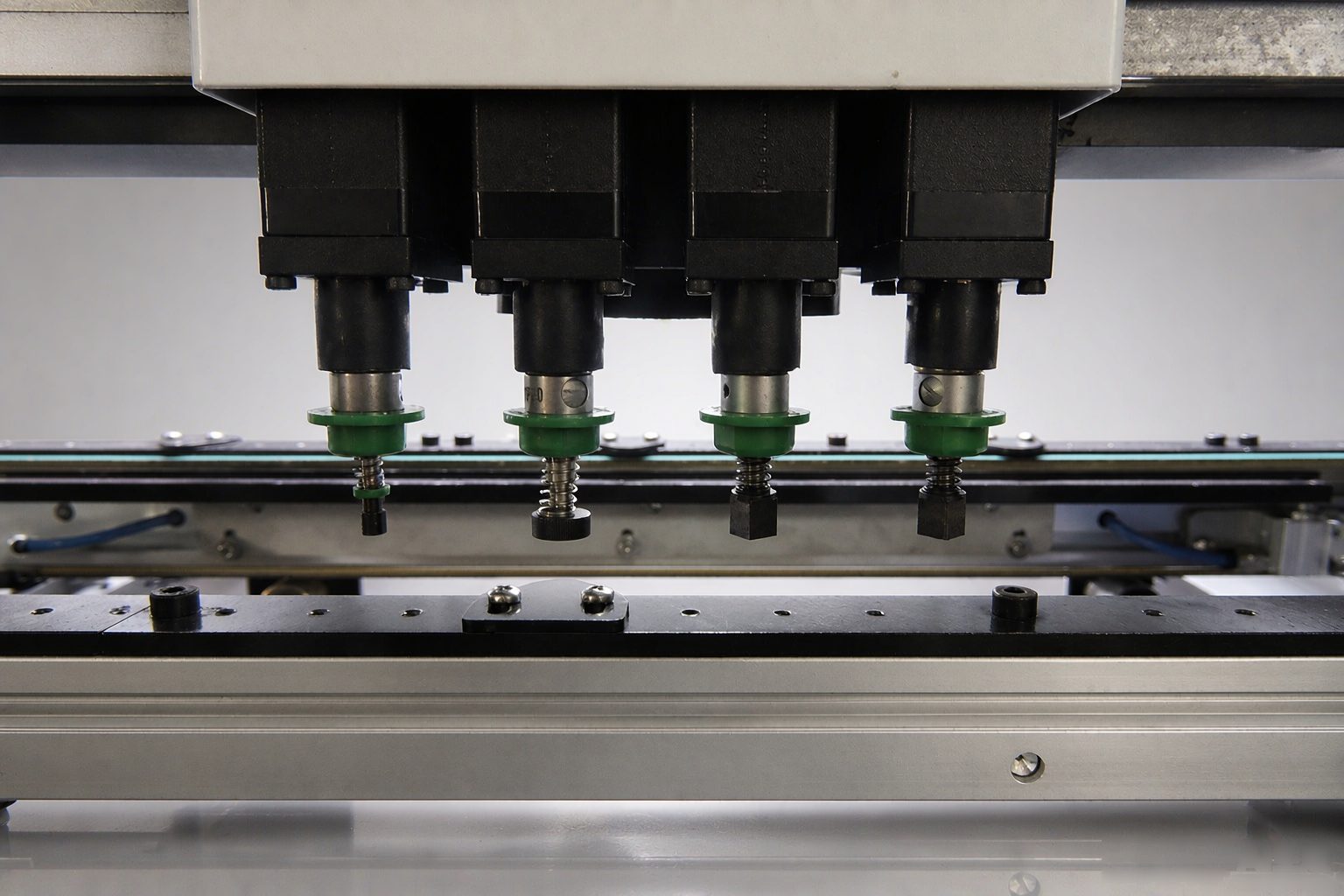
Shop floor photo: infeed and camera section of the vision labeling machine
This article is organized according to the typical configuration of similar production lines; specific parameters and configurations are subject to actual incoming materials and machine models.