
Conclusion
Among label feeder faults, the proportion that actually requires parts replacement is not high. Most cases are three adjustable areas that are not aligned: signal not connected correctly, fiber margin not set accurately, threading path and feed distance off. Checking in reverse order easily leads to wasted effort—adjusting feed speed and delay right away often throws off originally correct parameters, making the symptoms more chaotic.
First divide symptoms into three categories: completely no feed, two sheets at a time, fed but position incorrect. The three categories correspond to three different inspection paths, and the sequence below is organized according to the operation interface in the manual.
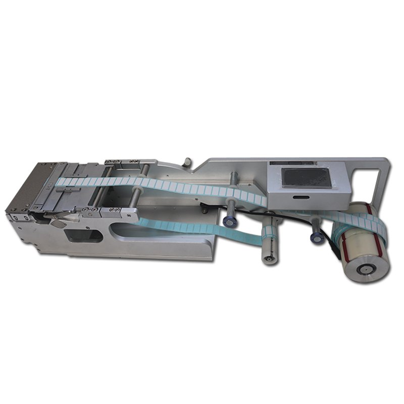 Label feeder overall appearance (JUKI compatible series)
No Feed: Check Power and Signal First, Then Detection
The feeder operating voltage is 24V, and the matching power supply current must be greater than 2A. The manual also specifically reminds not to share a power plug with high-power equipment—when the voltage is pulled down, the screen can light up, but the feed action will be intermittent, appearing like a program issue.
Signal wiring determines what triggers the feeder to feed. There are three settings in the interface:
- When the placement machine needs the feeder to provide a material-present signal, connect the yellow wire, set “Material Present Signal” to “Use” in the interface, and the feeder gives the placement machine a 0V signal when labels are present;
- When the placement machine needs to control the label output state, connect the green wire, set “Feed Signal” to “Use” in the interface, and the feeder only feeds labels after the placement machine gives a 0V signal;
- Set “Feed Signal” to “Not Use”, and the feeder automatically feeds by default when there is no label on the platform.
Only one corresponding wiring method can be selected for these three settings. If the green wire is connected but the interface is set to “Not Use”, the machine will not report an error, but the feeder will not wait for commands and will feed on its own—the manifestation is material stacking on the platform, and an extra sheet is already present when the nozzle comes to pick.
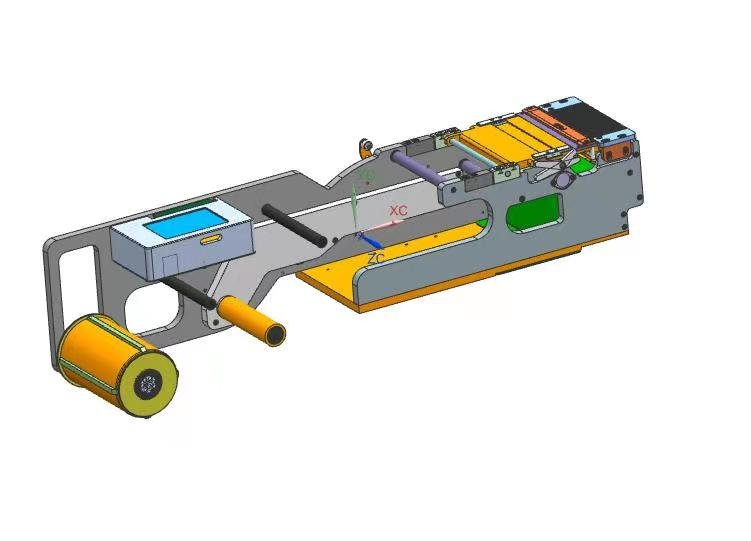 Feeder body and loading side appearance
Detection Stage: Fiber Margin 200 Is a Starting Point, Not a Fixed Value
The fiber sensor determines whether there is a label on the platform. There is only one setting rule: the working set value must be higher than the sensing value in the no-material state by a margin; the manual example is 200. During operation, when the set value is greater than the sensing value and the indicator light is on, material is determined to be present.
The margin is not copied as 200 for all materials. When the backing paper is translucent, the label area is small, or the color is light, the difference between material present and no material is inherently small, so the margin should be left wider; when labels are thick and strongly opaque, an excessively large margin will cause no-material detection to be delayed, and the feeder will continue feeding empty. For empty pickup and frequent false alarms, confirm this margin first before considering mechanical issues.
Offset and Double Sheet: Threading Path and Pressing Structure
During threading, the angle of the label strip must always remain straight; this is one source of position offset. The guide width-limiting slider is used to limit the label roll. Use a hex key to loosen the set screws inside, move the guide block to the appropriate position according to the label roll width, and prevent left-right swaying; adjust the height of the set screws at the four corners of the pressing plate according to label thickness. The label roll is clamped between the pressing cover and the driving shaft; press down the pressing cover to clamp it.
Double sheets mostly occur in the clamping section: the pressing cover not pressed fully into place, the guide block set wider than the label strip, and backing paper rebound during peeling can all bring out two sheets at once. Two other material-related details are written in the manual—for large labels or labels that are easy to peel, the spring winding shaft can be bypassed to avoid excessive angle causing premature peeling; for small labels that are difficult to peel, the peeling blade can be switched to the side with a smaller angle.
If the fed label tilts upward or is fed too much, the feed position is too large; if the label is not fed far enough, the feed position needs to be increased. After the feed speed changes, the feed position must be fine-tuned accordingly. When not pursuing placement cycle rate, setting the speed to 30–50 is sufficient; the feed delay is in units of 0.1 s, and it can be used to widen the cycle when the robot pickup is slow.
Different Models Have Different Adjustment Ranges
The parameters above exist on all roll-label feeders, but the adjustable ranges depend on the model. Taking several models from the model summary table as examples: LFSID-100 is compatible with ASM D series, label width 2–98 mm, number of columns 1–14; LFJUKI-32 is compatible with JUKI, label width 5–23 mm, single column; LFSUMSUNG-60 is compatible with Samsung (Hanwha), label width 2–58 mm, number of columns 1–8. For models with more columns and narrower labels, the guide block positioning accuracy is tighter, and alignment before pressing is even more important during threading.
Permissions and Warranty
The peeling blade and receiving platform must not be subjected to impact, nor operated with dirt or contamination; the housing, screen, interfaces, and other parts must be protected from insects, rodents, and foreign matter. The manual explicitly requires that installation, repair, addition, or disassembly be performed by personnel authorized by the company—damage caused by unauthorized disassembly is not covered by free warranty, and the warranty period is one year. Self-troubleshooting up to the parameter level is sufficient; for steps involving blade and transmission structure disassembly, it is more prudent to leave it to the manufacturer.
For equipment selection and compatible models, see the label feeder product line; for details on detection stage settings, see How to Set the Fiber Sensor.