
Conclusion
The trace labels, QR code labels and warning labels applied on automotive electronics lines are mostly roll-fed. Their widths range from a few millimeters to several tens of millimeters, and peel difficulty varies, yet the line does not want to change equipment for every material. What the feeding side can do is adjust three things by material: the threading path, the peeling method and the reel capacity, and leave the rest to the placement machine’s cycle.
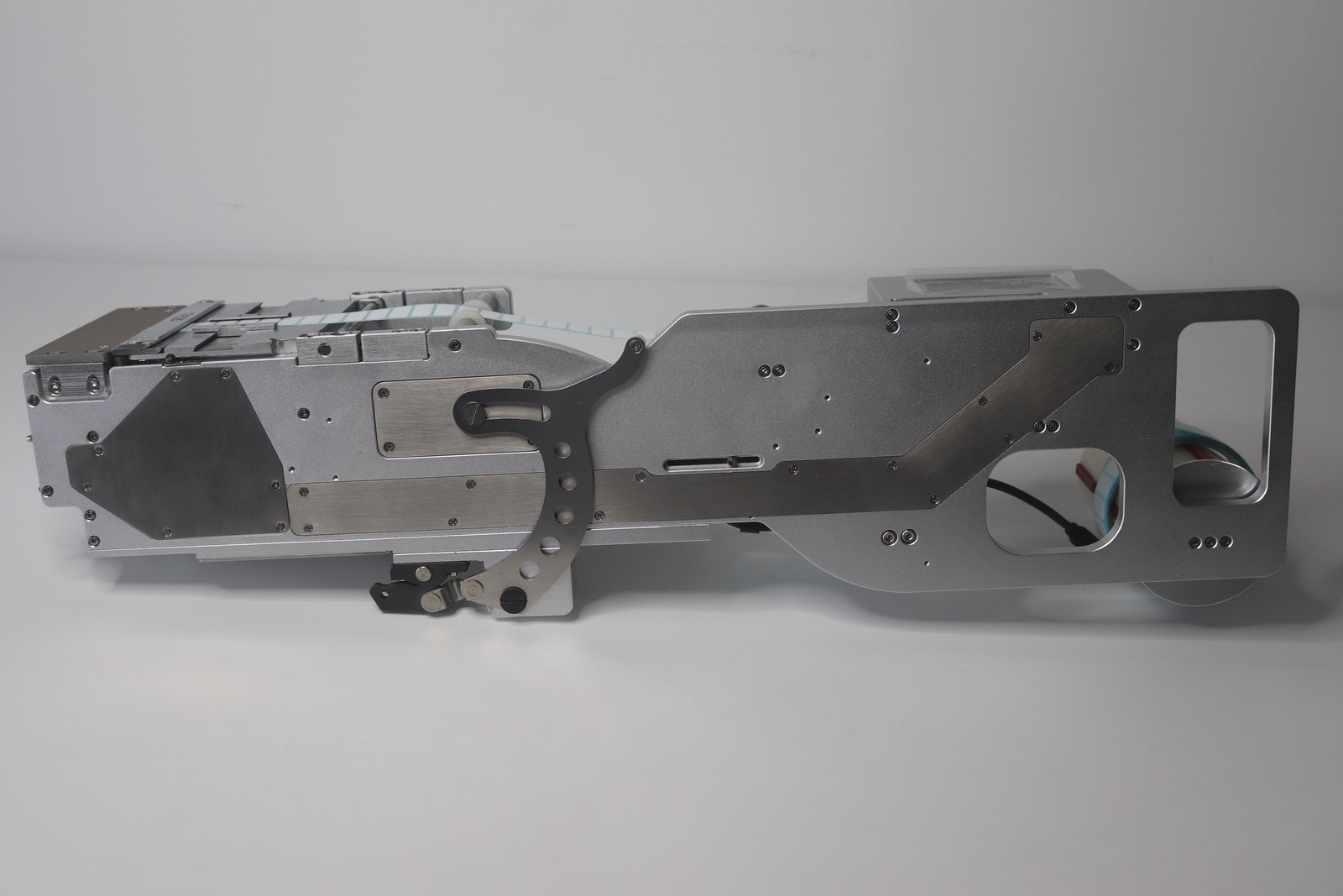
The BestFeeder label feeder manual lists applicable materials clearly: paper labels, FPC stiffener steel sheets, Mylar tape, foam, dust mesh, high-temperature tape and other roll materials can all be loaded; within the model’s size range, one feeder is compatible with materials of different sizes and supports single or multiple rows.
Three Requirements from Automotive Lines on the Feeding Side
- Long continuous operation. Automotive parts have long mass-production cycles, and equipment downtime directly affects delivery, so the feeding side must feed stably rather than jam frequently;
- Batch traceability. Production quantity and the count of each row of labels must be checkable, and the QR codes on labels must be readable;
- Many varieties, small batches. The same board may carry several kinds of labels, so material changes must be fast.
The first two fall on feeding stability, the third on the change rhythm.
Three Places to Adjust the Threading Path by Material
- Retaining ring limit: after the reel is fitted onto the label mounting shaft sleeve, use the retaining ring to limit the reel and prevent side-to-side sway;
- Guide width-limiting block: use a hex wrench to loosen the inner set screw, and move the guide block to the proper position according to reel width;
- Pressing piece height: loosen the four set screws of the pressing piece and adjust height by label thickness. Too loose, and the tape shifts up and down; too tight, and creases are left on the labels.
For materials with the adhesive side facing out, also check the anti-stick table material; Teflon coating, white silicone and red silicone can be selected by material.
Choose Peel Blade Orientation by Peel Difficulty
The manual gives two points on the peel blade: for small labels that are hard to peel, turn the blade to the side with a smaller angle; for large labels or labels that peel off easily, they can bypass the spring winding shaft to prevent premature peeling from an excessive angle.
Trace labels are getting smaller, and QR codes still have to be scannable; these two points are useful on small automotive labels.
Reel Capacity and Change Rhythm
The reel has an inner diameter of 76.2 mm and an outer diameter of 200 mm; other sizes can be customized. The larger the reel, the more labels a single load can run, and the fewer the changes.
When changing material, switch the working mode to manual; the feeder stops production for loading and changing. The production count on the touchscreen counts each row fed, and a long press clears it to restart counting. Together, these two let output be reconciled at shift handover.
Coverage of Label Width
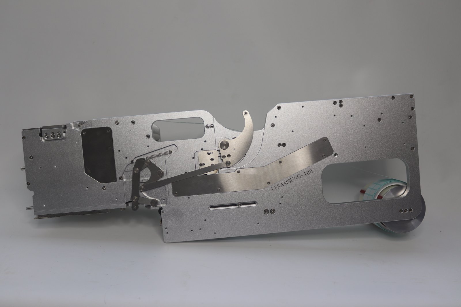
Width coverage depends on the model. In the standard on-screen feeder range from LFSID-60S to LFSID-250S, label width covers 58 mm to 248 mm; the classic LFS-60 / LFS-100 / LFS-150 correspond to three ranges of 5–58 / 5–98 / 5–148 mm; dedicated models divided by placement machine platform also differ in width coverage, for example LFSID-32 is 2–23 mm and LFSID-100 is 2–98 mm.
Trace labels on automotive boards are often made within 20 mm, while warning labels on module housings are wider. When selecting, first match the lower and upper width limits, then check whether the reel fits the slot.
Two Signals for Linking with the Placement Machine
- Feed signal: when the interface is set to “use”, the feeder waits for the placement machine to give a 0V signal from the green wire before feeding; when set to “not use”, the feeder feeds automatically when there is no label on the table;
- Material-present signal: after the interface is set to “use”, the feeder gives the placement machine a 0V signal through the yellow wire when labels are present.
To follow the placement machine’s cycle and avoid empty feeding, let the placement machine give the feed signal; to let the feeding side keep labels at the pick position on its own, use automatic feeding. Set the fiber optic working value 200 above the no-material state; this is the starting point given in the manual.
What to Include When Reporting Specifications
Label type and pattern, width and thickness, backing paper material, usage per board, reel specification, placement machine model and model series.
Further reading: Label Feeder, New Energy Battery Modules: How to Automatically Feed Insulation Sheets and Warning Labels.