
Conclusion
This EMS plant in South China has four SMT lines running high-mix, low-volume orders with three to five changeovers a day. Labels were previously applied manually piece by piece at the end section; during changeovers the labeling station had to wait for scheduling, and off-position labels required rework. After installing the LFSID-100S L/R, labels enter the same placement program as components, and material changes shift from “line stop waiting for manual work” to “reel swap at the station.”
Production lines and how labeling was done before
The four lines run low-volume orders, and a single board usually has only one or two label positions: a serial number QR code, a model label, and on a few models a certification label. Batch sizes range from tens to hundreds of pieces, and changeover frequency affects delivery dates more than single-line output.
The previous approach kept labels off the line: a labeling station was set up at the end section, and labels were manually aligned and applied per board type. During changeovers, this station had to wait until the previous line’s boards were finished before it freed up; labels also had to be re-sorted by model, and misaligned labels had to be peeled off and reapplied, leaving adhesive residue on the board surface.
Selection and configuration
There were two direct reasons for choosing the LFSID-100S L/R.
First, the label size span. Labels in use at this plant range from QR codes around ten-plus millimeters wide to model labels over eighty millimeters wide. The LFSID-100S handles label widths of 5–98 mm and label lengths of L2–40 mm, so one model covers all labels in use. The body measures 450 × 135 × 320 mm and weighs 8 kg; it uses a feeder-station interface and mounts at a standard feeder position. The number of columns is set by the label types in the program, and the 1–8 column range covers the current order structure.
Second, the space above the feeder station. The -S is a short upper-screen structure with a lower body height than the long structure, so when mounted at upper-row feeder stations it does not hit the inside of the machine cover or block the pickup path of adjacent feeder stations. Left-top loading (L) and right-top loading (R) are both available; the four lines do not have identical feeder layouts, so changeovers need not be limited to a fixed station.
Setup and commissioning
Installation has four steps: push the feeder into the station and lock it, take the pickup signal and vacuum from the placement machine, thread the material, and align the fiber sensor. Station height is calibrated to the feeder standard of 20 mm; if the height is off, the nozzle pickup height deviates as well. Thread the material on the peel-blade side, pass the backing paper through the middle of the guide block with labels facing up; set the fiber sensor’s operating value according to backing paper light transmission, with the threshold placed above the no-material reading.
Two areas took more time during commissioning: first, label width spans. Moving the same feeder from QR codes to model labels requires swapping a set of guide width-limiting blocks and re-aligning the fiber sensor afterward; if two widths with a large difference are switched repeatedly on the same day, equip two feeders by width. Second, peel position: calibrate the first article with a scale plate, measure the distance from the peel blade edge to the nozzle pickup position accurately, and recheck after each label width change.
Changes after going live
The change is in the sequence of changeover actions: previously the end-section manual labeling had to clear the line before the new model started; now the program switches to the new model, the feeder follows the station address, labels are applied together during placement, and the end section no longer schedules a separate labeling station. The person who previously did labeling on that line moved to visual inspection and packaging.
Label placement position is determined by machine coordinates, so repeated production of the same board type yields consistent positions with no manual alignment variation. First-article inspection is done together with PCBA first-article inspection, and the inspection record notes the label position coordinates and peel status.
At acceptance, the customer confirmed that “the end section no longer has a dedicated labeling position,” and the reduced headcount follows their shift schedule. Changeover time and yield are subject to the customer’s statistical criteria and are not cited in this article.
FAQ
Does each of the four lines need its own feeder? It depends on order scheduling: lines with high changeover frequency get their own feeder, while lines with fewer changeovers share a few feeders. Feeders move with the work order along the line, and the interface and signals are the same set.
How to choose between the -S short structure and the long structure? Look at clearance above the feeder station and spacing to adjacent stations: choose -S when space is tight and mounting at upper-row stations; evaluate the long structure when more lanes are needed.
What if label width changes frequently? For large spans, use two feeders by width; for small spans, swap a set of guide width-limiting blocks and re-align the fiber sensor, then recheck peel position afterward.
To verify compatibility by placement machine model and label size, contact us directly: Kenny Pan · Sales Manager · Phone/WeChat +86 134 2139 1163 · Sales@baxida-tech.com
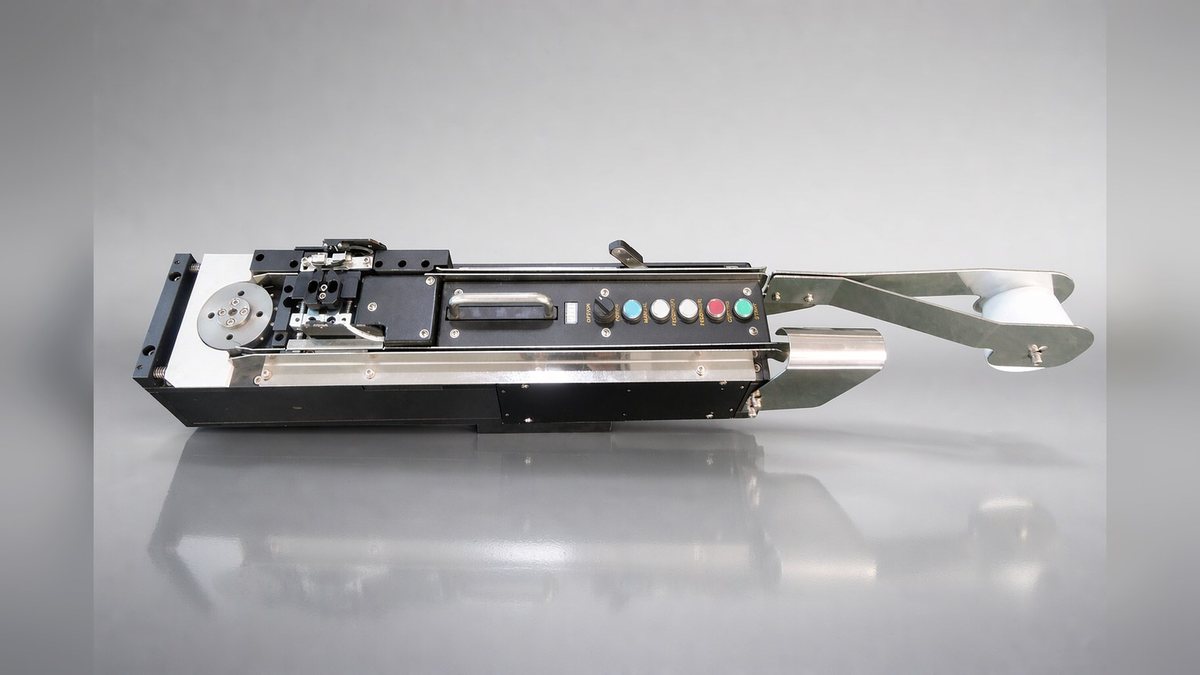
Equipment photo: LFSID-100S L/R reel label feeder
This article is a scenario illustration of typical operating conditions, not a specific customer project; actual configuration is subject to selection confirmation.